
How to Choose the Best SMA Antenna for Your Needs

Choosing the right Sma Antenna is not simply a matter of selecting the highest gain on a product page. Frequency range, impedance, radiation pattern, cable loss, connector fit, and installation space all affect real-world performance. A compact antenna on a metal enclosure, for example, may behave differently from the same model mounted in open air. Small details matter.

The wider wireless landscape makes careful selection increasingly relevant. GSMA’s The Mobile Economy 2024 projects 5.5 billion 5G connections worldwide by 2030. That projection does not describe the SMA antenna market specifically, but it highlights the growing need for dependable radio-frequency links across connected devices. For a practical foundation, antenna engineer Constantine A. Balanis writes, “An antenna is a transitional structure between free-space and a guiding device” in Antenna Theory: Analysis and Design. The phrase captures why the antenna must suit both the radio and its surroundings.

A useful comparison starts with the device’s operating bands and 50-ohm system, then checks connector gender, cable length, and mounting method. Compare gain and radiation patterns, not gain alone. A high-gain model may be a poor fit if its coverage pattern misses the intended direction. Check the datasheet, and verify the installed setup when possible. There is no perfect pick. And published specifications do not always predict performance inside a crowded enclosure. That is worth remembering before buying.
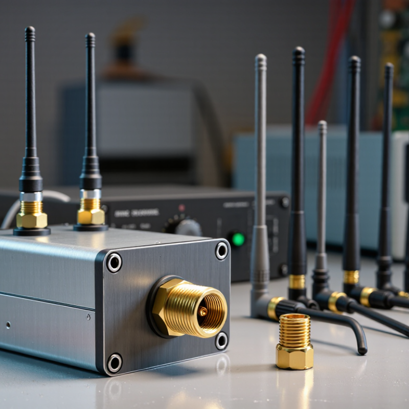
How to Choose the Best SMA Antenna for Your Needs

Identify Your Device, Use Case, and Antenna Requirements

How to Choose the Best SMA Antenna for Your Needs

Start with the device’s exact radio frequency, not the label on its case. Check its manual or measure the antenna port, then confirm the SMA connector type and gender. Also verify that the antenna supports the device’s transmit and receive bands. A connector that fits can still be electrically wrong. 3GPP Technical Report 38.901 models radio channels from 0.5 to 100 GHz, underscoring how widely operating frequencies can vary. A “5G antenna” label alone tells you too little.

Next, match the antenna to the real use. A fixed gateway beside a window may benefit from a directional antenna aimed toward the signal source. A handheld device usually needs an antenna that works across changing orientations. Check gain, radiation pattern, mounting space, and cable length; long, thin cables can add signal loss. A neat specification sheet can still mislead if it ignores your surroundings. Concrete walls and metal cabinets matter.

Tips: Write down the device model, operating bands, connector, and mounting location before shopping. Compare the antenna’s frequency range with every band you need, then check its datasheet for gain and cable-loss figures. Test placement if possible. Small shifts can help.

Match the Antenna’s Frequency Range to Your Application

How to Choose the Best SMA Antenna for Your Needs

Match the antenna’s frequency range to the frequencies your device actually uses. An SMA connector only describes the connection; it does not guarantee that an antenna will perform well across every band. Check your radio or module specifications, then compare its operating frequencies with the antenna’s stated range. If your device uses several bands, confirm that each falls within the antenna’s rated bandwidth. An antenna that is close, but not quite within range, may still connect physically. Its signal performance can suffer.

Tips: Check the exact frequency range, not just a label such as “wideband.” Also verify connector gender, impedance, and any stated gain. Small details matter.

Think about where the antenna will sit. A compact antenna mounted beside a metal case, cable bundle, or wall may behave differently from one tested in open space. A clear placement and a suitable frequency match often matter more than a high gain figure. I’ve seen people focus on the connector first, which is understandable, but frequency compatibility is the better starting point. Specifications are not a promise of identical results in every setup, so test the antenna in its intended location when possible.

Check SMA Connector Type, Gender, and Polarity

An SMA antenna can look compatible and still fail to mate correctly. Check the connector itself, not just the product listing. Standard SMA male connectors usually have a center pin and external threads; female connectors have a center socket and internal threads. Reverse-polarity SMA changes the center contact, not the outer-shell gender. That small difference matters: a pin and socket must match, while the threaded shells must also engage. IEC 61169-15:2015 specifies the SMA connector interface, but it does not guarantee that every antenna assembly supports the same frequency range.

Match the antenna’s connector type and polarity to the radio or cable, then confirm impedance. SMA systems are typically 50 ohms; a mismatch can increase reflections and reduce delivered signal power. Common SMA assemblies are often rated up to 18 GHz, but actual limits depend on construction and the antenna. Check the datasheet rather than assuming the connector’s appearance proves its rating. A close-up photo helps: count the center contacts and inspect the thread direction before ordering. I still double-check. “Male” and “female” labels can be used inconsistently in listings, so compare the written specification with the physical connector.

Compare Gain, Radiation Pattern, and Antenna Design

Choosing an SMA antenna starts with matching its frequency range to your device. Then compare gain, radiation pattern, and physical design. A higher gain rating is not automatically better. Gain concentrates transmitted or received energy in certain directions, which can help across an open field but create weak spots nearby. Check whether the rating is stated in dBi, and compare antennas under similar test conditions.

Radiation pattern describes where the antenna performs well. An omnidirectional model can suit a sensor that moves around a room, while a directional model may work better for a fixed link between two points. Picture a small antenna mounted beside a metal enclosure: the case, cables, and nearby surfaces can distort the expected pattern. Test the antenna in its final position when possible. The numbers alone miss things.

Design affects both performance and fit. A short whip may be easier to mount, but its size and ground-plane requirements can limit performance. A hinged antenna offers positioning flexibility, though that joint adds another point to inspect. Confirm the SMA connector type, available clearance, and cable strain before ordering. One detail is easy to overlook: a connector that fits physically may still be the wrong gender or orientation. Check the device documentation, and treat published gain as a useful reference, not a promise of identical results in every installation.

How to Choose the Best SMA Antenna for Your Needs — Compare Gain, Radiation Pattern, and Antenna Design

Antenna Design Typical Realized Gain Radiation Pattern Design Characteristics Best Suited For Key Considerations
Quarter-wave monopole About 0 to 2 dBi Approximately omnidirectional around the antenna in the horizontal plane; strongest broadside to the antenna axis. A straight conductor approximately one-quarter wavelength long, typically operating against a conductive ground plane. Compact wireless devices where coverage is needed in multiple horizontal directions. Performance depends strongly on the ground plane, mounting position, and nearby materials. The antenna length must suit the operating frequency.
Half-wave dipole About 2.15 dBi in free space Omnidirectional around the dipole in its broadside plane, with reduced radiation along its axis. Two conductive sections with a total length close to one-half wavelength; generally does not require a large ground plane. General-purpose links when a balanced, predictable pattern is useful. Requires enough clearance for the antenna and feed arrangement. Nearby objects and the device enclosure can alter its pattern and impedance.
Loaded or shortened whip Commonly about −3 to 1 dBi Usually broadly omnidirectional in the horizontal plane, though the pattern may be less uniform than that of a full-size antenna. A physically short radiator that uses loading or matching components to operate below its natural quarter-wave length. Portable equipment where reduced size and lower snag risk matter more than maximum efficiency. Shortening generally reduces efficiency and bandwidth. Confirm performance on the final device, not just in free space.
Flexible whip About 1 to 5 dBi, depending on design and frequency Generally broad horizontal coverage; bending or nearby structures can distort the pattern. A flexible conductor or helical element, often longer than a compact loaded antenna and designed for a specific frequency band. Mobile or handheld devices that benefit from a flexible, replaceable external antenna. Check the antenna’s specified frequency range, connector orientation, clearance, and approved bend limits.
Directional patch About 5 to 9 dBi for many compact designs Directional, with a stronger forward lobe and less coverage behind the antenna than an omnidirectional whip. A flat radiating element, commonly mounted over a ground plane and connected through an SMA feed. Fixed or aimed links where stronger coverage in one direction is more useful than all-around coverage. Alignment matters. Verify polarization, beamwidth, mounting orientation, and the space required behind the radiating face.

Selection note: These gain figures are representative ranges, not guaranteed specifications. Actual realized gain and radiation pattern vary with operating frequency, antenna matching, ground-plane size, enclosure, cable, mounting, and nearby objects. Select an antenna specified for the exact frequency band and verify its performance in the intended installation.

Verify Size, Mounting, and Environmental Compatibility

An SMA antenna must fit the device, not just the connector. Check the antenna’s overall length, diameter, and bend clearance against the available space. A compact enclosure may block part of the radiator or press against nearby components. Confirm the required frequency range in the equipment documentation; SMA describes the connector, not the antenna’s operating performance. Also check whether the device uses a standard SMA or a reverse-polarity variant. They can look deceptively similar.

Tips: Measure the mounting area before ordering. Note the panel thickness, connector thread, and any required ground plane. Leave room to tighten the antenna without twisting its cable. Small details matter.

Consider where the antenna will operate. Outdoor exposure may call for suitable moisture and UV resistance, while vehicles or machinery can add vibration and temperature swings. Check the stated operating range and sealing details rather than assuming a rugged-looking housing is weatherproof. For a panel mount, make sure the surface supports the antenna securely and that water cannot collect around the opening. A flexible joint may help with impact, but it can also shift under repeated movement. Fit is not always obvious on paper. A careful test in the actual enclosure can reveal blocked clearance or weak reception, though one location may not represent every installation.

How to Choose the Best SMA Antenna for Your Needs

Verify size, mounting, and environmental compatibility before selecting an antenna.

The bars show theoretical free-space quarter-wave lengths, calculated as the speed of light divided by four times frequency. Actual antenna dimensions can differ because of design and tuning. Confirm the antenna’s frequency range, SMA connector type and clearance, mounting method, and suitability for moisture, temperature, and other site conditions.

Article Source: